
In the latest 5G Guys podcast episode, hosts Dan McVaugh and Wayne Smith interview Jeff Vaughn with Douglas County Sheriff’s Office and our very own Cody Martin on the important topic of public safety communication in schools.
They share common pitfalls as well as unexpected impact, and provide an overview of the work done by Castle Rock Microwave to enhance in-building communication.
From infrastructure to security, get 24/7 monitoring of your systems to ensure that when outages or issues occur, you’ll be able to react quickly with expert support.
Get in touch with a member of our team to learn about Lifecycles Services and how the service can support your organization’s communication network.
With Lifecycle Services, you can:
When you trust us to keep an eye on your systems with Lifecycle Services - we aim to find issues before you do.
Want to learn more? Reach out here.
Whether you're experiencing networking issues, wondering how to maximize your return on technology investments, or have a question about growing leased-line circuit costs, reach out anytime.
The City of Aurora is a Home Rule Municipality located in Arapahoe, Adams, and Douglas counties, Colorado. Aurora lies immediately east of Denver. It is one of the principal cities of the Denver–Aurora–Lakewood, CO Metropolitan Statistical Area and a major city of the Front Range Urban Corridor.
The City trusts Castle Rock Microwave to help them overcome their wireless connectivity challenges. As a result, they turned to CRM when they were looking to upgrade connectivity at several community locations in late 2020.
Castle Rock Microwave suggested wireless solutions from Cambium Networks in 60 and 80GHz. These millimeter wave frequencies are ideal for achieving fiber-like speeds at a fraction of the cost of building new fiber infrastructure.
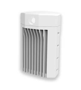
We recommended the PTP850E for 80GHz and cnWave v5000 and v3000 for 60GHz. The PTP850E is an ultrahigh capacity, all-outdoor backhaul that delivers up to 20 Gbps capacity. The cnWave uses Terragraph, Facebook’s new terrestrial connectivity technology.
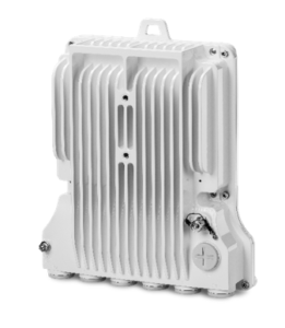
PTP850E
cnWave v5000

cnWave v3000
Terragraph opens up a new way to use the large amounts of unlicensed spectrum available in the 60 GHz millimeter Wave band, using a mesh architecture that can be used for many FWA, backhaul, smart cities and IoT use cases. With the increase in demand for gigabit connectivity and the availability of commercial equipment, Terragraph has become a hot technology, with the first large commercial deployments expected in 2021.
To find out more about Terragraph and the opportunities it offers to service providers, cities and enterprises, register here to receive the report that will be available soon, or download the interviews that will be part of the report as they become available.
Photo by Vlada Karpovich on Pexels.com
In 2020, rural telcos that provide wireless internet access have seen many rapidly developing events that have impacted their businesses. Instantaneous increases in demand due to COVID, RDOF applications, CBRS Auction and CARES Act money/grants have been pushing rural telcos to optimize network performance and capacity. In this article, I will address some of the performance issues rural telcos with broadband services are seeing and solutions to optimize wireless networks.
This increased demand has left many providers struggling to keep up to their overtaxed networks. In addition, they are having problems providing reliable service and their customers are starting to look for better alternatives.
In a recent article , Mike Dano states, “As office workers, students and others continue to seek shelter at home from COVID-19, demand for speedy and reliable Internet service appears to be at an all-time high. That demand is beginning to have serious effects on the nation’s telecommunications providers.” “Capgemini recently surveyed 6,300 US consumers and found that almost half (48%) felt their Internet connections didn’t meet their needs. The firm also found that customers are increasingly looking at their connection’s flexibility and network speeds, rather than just the reliability and price.”
With so much expansion occurring within internal networks and competitors’ networks, interference can slowly creep in degrading performance.
New users and greater capacity demands are now exposing issues with bandwidth management. Furthermore, poor bandwidth management from inefficient design practices decreases available bandwidth and decrease capacity in the distribution network.
There are solutions, but there are often tradeoffs as well. The decisions on performance are being driven by market demand and existing capacity. With rapid expansion of user expansion and bandwidth demand, your wireless access points and network can quickly become overburdened. Start with an audit of RF performance by an RF expert to see which problems you are experiencing.
One solution is using more directional antennas at access points. This will help performance by:
Another solution is using smaller cells or micro PoPs. This can increase capacity, improving the user experience. Each access point is limited the least common denominator of capacity its users are receiving. As a result, wide ranges of distances from the access points can play havoc on performance. Therefore, tighter variances and shorter distances will help set customer expectations.
Adding capacity is an obvious solution. 25/3 is no longer the real standard, users are now demanding 100’s of Megs or even Gigabit capacity. There is a new disruptive carrier class PTP option pushing multiple gigabits per second. And it is one of the most cost-effective solutions in terms of cost per megabit per second per mile. This product provides the highest capacity in a single transceiver radio with 2.5Gbps (single radio – 2x112MHz channels) or 1.5Gbps (single radio – 2x80MHx channels) at 4096 QAM. For more information on implementing this system, please visit our Case Study with South Park Telephone Company.
For the distribution network, implementing massive Multi-User MIMO or MU MIMO solutions will provide greater access to users and capacity. Many carriers are using less robust, standard MIMO solutions and are reaching user density thresholds. Accordingly, they need a technology leap to support more users at higher capacity. Cambium’s PMP450m (cnMedusa) is a high-capacity multi-point solution that can provide more than 400 Mbps actual usable throughput per sector, and communicate with up to seven Subscriber Modules simultaneously. With 8×8 MU MIMO it provides 4x more spectrum efficiency than any other vendor. It also impressive Near or Non-LOS capabilities as well for more flexible installations.
Purchasing microwave equipment is a long-term decision with implications on future needs, sustainability, and total cost of ownership. A few years ago, Brett Bonomo wrote an article on this topic that covers key questions to ask including:
For more detail visit the complete article at https://castlerockmicrowave.com/selecting-the-right-radio
Would you feel more comfortable hearing from others when evaluating technology? Great, there is a great Facebook page that hosts over 10,000 members where you will likely find answers to your many questions from companies much like yours.
CBRS (Citizens Broadband Radio Systems) is now being considered by many telcos for a last mile solution. If you are not familiar with this newly available spectrum (3550-3650MHz), here is a quick article on CBRS
What are some of the key advantages of CBRS?
With fewer issues of interference and more flexible antenna locations this means happier customers and fewer truck rolls to tweak your network.
Companies operating CBRS networks need to employ someone with a CPI, either directly or via consultancy. There are many online training courses to get certified. Make sure the training course registers you in the WinnForum CPI database and send your credentials automatically.
Castle Rock Microwave can assist you with a coverage comparison analysis or try it yourself if you are familiar with LINKPlanner (Cambium Networks) or Pathloss software.
Castle Rock Microwave is a turnkey, regional system integrator for microwave backhaul, fixed wireless broadband and WI-FI solutions for Rural Telcos, Utility Companies and Public Safety agencies. We view your wireless system as an integral part of your operation and create holistic RF designs with your entire systems, sustainability, and future business goals in mind. We are vendor agnostic and work with our clients in choosing the best solution for performance, maintainability, and budget in mind. Call us for:
Current market conditions are creating opportunities for rural telcos to expand their users and networks and in some cases with substantial grants. Wise long-term investments in the correct gear will separate the leaders from the competition. Make sure your designs are considering all the factors when deploying or optimizing your wireless network and contact Castle Rock Microwave for help at sales@castlerockmicrowave.com or call 303-358-7039.
An industry test equipment manufacturer recently estimated up to 40% of all wireless microwave paths are not aligned optimally. We believe it’s more, perhaps as high as 60%, or higher. Of course, it’s a difficult assessment to make. However, we frequently troubleshoot installation issues and have observed thousands of deployments.
Optimal antenna alignment ensures the following:
1. Regulatory and frequency coordination compliance
2. Maximized system performance
3. Predictable system availability
There are several factors that impact proper antenna alignment. First, one must consider the appropriate antenna construction and installation. Secondly, the proper mounting hardware and installation. Next, the installer and weather are taken into account. Finally, the procedures and the equipment employed to perform alignment.
In our experience, the fewer parts required to perform field installation, the better. Occasionally, we have to install antennas we don’t like. In those circumstances, it is best to build the dish in a controlled environment before transporting it to the site. This is particularly helpful when a dish comes with a lot of small parts. Following this strategy minimizes potentially costly issues while on site.
The source of the alignment problem often stems from the mounting hardware. In many cases, it’s not appropriately sized for the dish or the pipe mast is not perfectly plumb. We have found that adjusting a dish through anything other than a single plane will result in completely unpredictable results. Installers forego perfect leveling of the pipe for a lot of reasons, but here are the most likely:
* Not properly educated on the importance of a perfectly level pipe
* Improper mechanical hardware to compensate for a tapered tower or uneven mounting surface
* The wrong tools and no level
* Fatigue
* Laziness
It should be obvious that mating the correct sized pipe clamps to the correct sized pipe is necessary. Unfortunately, we often see corners being cut as a way to save time and money.
The best way to ensure the dish mounting mechanism is installed properly is to require plenty of pictures. Doing so will remove any doubt that it was done incorrectly. Most importantly, pictures of a level placed on both axes of the pipe mast proves it is indeed perfectly level. This will help rule out any issues with the mounting hardware. In addition, you should include a photo with level on the back of the dish. This will show that the dish is level.
When proper alignment becomes difficult to achieve, and all other possibilities have been eliminated, it’s time to consider the installer. It can be physically and mentally grueling to spend hours on a tower performing the same procedure over and over, and not improving the situation. Nine times out of ten, the installer and their support people on the ground resign to the frustration and lack of discipline of proper alignment and just settle for low RSL.
I have witnessed proper alignment take multiple attempts by inexperienced people, until the “right person” arrives. Of course, the more experience someone has, the better they get at it. In fact, some installers can pre-align a dish with a high degree of success using simple navigation tools like a compass and nearby landmarks.
A favorite saying I’ve heard is that, “Plan B is not Plan A, with enthusiasm”. Sometimes it’s necessary to give the project a rest and come back to it, or put a new set of eyes and hands on it.
It’s very difficult to install relatively large dishes in the wind. Likewise, dishes that sustain exposure to high winds can move over time. It’s critical that appropriate tie-back hardware is used on larger antennas. Some customers require that 3′ dishes and larger have tie-back hardware. Often 6′ dishes have two tie-backs and 8′ dishes and larger have three tie-backs. The use of tie-back hardware (sometimes called “struts”) requires forethought and planning, to ensure that all of the correct hardware is purchased in advance.
In areas where propagation is more susceptible to inversions and weather-related phenomena (varying k-factor), it is very important to perform alignment during periods of stable weather. Generally speaking, ‘good’ propagation is accompanied by wind and sun, cold fronts can be good – once they pass, warm & stationary fronts are ‘bad’. I credit my friend and colleague, Tom Hendricks for this information.
Anticipate challenges in antenna alignment when shooting over or through reflective surfaces (ie large bodies of water or between many tall buildings or a narrow canyon). With a good design the results are predictable.
We often use the microwave radio to provide fine alignment of the system. Most radios provide an indication of Received Signal Level (RSL), sometimes called RSSI. One should always be aligning to a planned RSL (dBm) value, which is derived from path planning tools or software. In addition to providing an RSL value, some radios also give audible feedback with a buzz or beep, or visual feedback with LEDs. Regardless, we generally only use these aids for course alignment and rely on an RSL measurement for fine alignment.
On occasion, the antennas are being installed before the radios are available, so the radios cannot be used for fine antenna alignment. There are some popular products available for antenna alignment under these circumstances, like the Spectracom Path alignR.
Similarly, we recently witnessed a demonstration from a company called Sunsight Instruments and their alignment tool called the AAT-08. We found it to be a highly innovative tool and seemingly valuable in terms of expediting alignment, versatility and reporting capabilities. We’re anxious to get feedback from the field about how they work.
To reiterate, the right tools need to be used. This is typically ratcheting-style wrenches and socket sets of the correct size. In addition, a small torpedo level to ensure everything is perfectly plumb prior to alignment. We often see people using digital levels. These seem to work well. Your installer should also use a marker to put an indicator on the threaded rod. This will remind them how to get back to a certain signal level.
Prior to getting on the tower or building, a course alignment can be achieved using a simple magnetic compass, adjusted for proper angle of declination. Of course, this assumes that the path azimuth is known. Google Earth can help identify nearby and distant landmarks that the installer can use to aim the dish.
We always align the antennas with no up-tilt or down-tilt, unless the path is extremely short. This is the easiest way to begin alignment if the expected tilt adjustment is less than a couple of degrees.
Only one side of the path should be adjusted at a time. In addition, everything below assumes that both dishes are on the same polarization.
Once everything is level, the azimuth should be swept. You’ll often see one or more side lobes of the antenna before you see the main lobe. This is indicated by the RSL measurement. The main lobe is often distinguishable as having approximately 20dB more signal than the nearest side lobe. Likewise, it tends to rise and fall off very sharply, where side lobes can persist longer through a sweep cycle. Also, the main lobe is accompanied by the presence of at least two side lobes on either side of it.
If you were to start a sweep on the far left side of the radiation pattern of a dish, sweeping the dish to the left (pulling the left side of the dish towards them), you should see some amount of signal gradually increase and then decrease (one side lobe). Next, you will see the signal increase more than it did with the prior lobe and then decrease (another side lobe). Finally, the signal should increase significantly (~20dB) and quickly fall off. This is the main lobe. After this, the reverse of what was just described should be witnessed as the dish continues to be swept in the same direction, until the signal completely goes away.
Commonly, installers will only see a single lobe in the entire sweep. This is seldom the main lobe and evidenced by a signal level well below (10 – 20dB) the planned RSL. A lot of time is often spent aligning both sides of the link to keep landing on the lower-than-expected RSL. This is often due to one of the issues described above. Either mounting isn’t level, there’s tilt in the dish, or adjustments are being made on both side simultaneously, etc.
Another common symptom of poor alignment is that two rises and falls of signal will be seen, but well below the expected amount. This is just more evidence of either being above or below the main lobe, or not sweeping far enough through the entire radiation pattern.
Once the main lobes of both dishes are found, the elevation should be adjusted to optimize the link. Once both azimuth and elevation are fine tuned, the RSL should meet the planned signal level dictated by the path design.
There are definitely other things that can go wrong with microwave radio links. More often than not, the problems stem from a system that isn’t optimized. The most neglected step in optimization is proper alignment.
We’d love to hear your thoughts on the matter. Please take a moment and let us know how you deal with an installer or tower crew that swears the path is “on the main lobe”, when all of the evidence points to it being on a side lobe.
Don’t forget to click here and sign up to receive our latest blog posts and free content.
Selecting the right microwave radio manufacturer is difficult, even for a seasoned microwave professional. In this post I’ll share some questions you can ask radio manufacturers. Hopefully, you will have the confidence to navigate the competitive landscape and identify a solution that exceeds your expectations.
We recently conducted a customer survey where 30% were unsatisfied with or uncertain about their current microwave manufacturer. Another 20% asked us for assistance on the matter.
The equipment vendor landscape is growing. In addition, differentiating between them has become increasingly difficult. If you don’t have a trusted source to help you identify the best solution, you need one. At Castle Rock Microwave, our clients trust us to guide them through this process by performing a needs assessment. Once we understand today’s needs and future goals, we make it easy to navigate the many options. It’s easy for them to trust us because we are not a manufacturer. Because we represent multiple manufacturers, we offer guidance based on their needs and not solely on our own interests. If you don’t have a trusted expert to help guide you through this process, here are some questions you can ask your potential radio vendors.
To answer this question, you need to ask a couple more. Do your best to understand how the product is distributed. Is it through a sales channel or direct from the manufacturer? If through a channel, would you buy from a reseller or distributor? Besides distribution of the product, you need to understand availability of it. Is product generally available “off the shelf”? This can be hard to verify unless you trust the manufacturer representative or channel representative.
It’s important to realize most vendors are operating with “just in time” manufacturing. This is why most sales reps call you incessantly. They need to track their forecast on a regular basis. Product availability should also factor into your decision to stock spare equipment or buy advanced support contracts. If you or your customer don’t have the budget to maintain spare equipment, then working through a channel that can provide immediate turn-around is important. Many manufacturers have support contracts to accommodate next-day delivery of replacement equipment.
Ultimately, you need to understand how product availability could impact your day-to-day business. Don’t make assumptions here. You need to know if the manufacturer you select can get you equipment when you need it.
Take the time to understand availability of technical support. This service differs from free to only available under contract, depending on the vendor. Some support contracts only entitle you to support during normal business hours. Others offer 24/7/365 assistance.
In some cases support is non-existent. Some vendors rely entirely on their user community to provide support. This approach is clever and incredibly cost-effective for the manufacturer and customer. However, it’s only suitable for certain types of customers.
Similarly, consider how much you want to rely on your distributor or reseller for support. Ideally, the sales channel would be responsible for the majority of the stock and support would only be escalated to the manufacturer for the most critical issues.
Few manufacturers have stuck to their guns in this regard. I used to challenge prospective customers of mine to pick up the phone and attempt a phone call to the manufacturer support line. Better yet, stage a support issue and see for themselves what the experience is like. The same can be done by email. Even if you don’t go through the motions, any indication of responsiveness is helpful.
Your manufacturer, distributor, or reseller should explain the options available and costs associated. You should always ask for current customer references. It’s even better to do a little leg work and find an existing customer or two who will give you their honest feedback.
There are other intelligent questions you should ask about mean time between failure (MTBF) and mean time to repair (MTTR). However, we tend to find that even when provided, these numbers always look better on paper than in reality.
It often seems there are more similarities between manufacturers than differences. This happens less if your requirements include specific IP networking or TDM capabilities.
The playing field is fairly level for IP-only (bridging) radios. The exception here is a very narrow segment of the industry that optimizes radios for low latency. These products are primarily used by high frequency trading firms.
There are some differentiating themselves with features that enable scalability to impressive capacities, simplicity in sparing equipment, smaller form factors and less power consumption. There seems to be increasing requirements for IT-related features and security, which vary slightly by industry, but seem to be converging.
These are requirements that enable different degrees of access and control of the management interface and flexibility in handling Layer 2 functionality. There are many vendors today that tout impressive Layer 3 (routing) capabilities. If you need to include Layer 3 functionality, it’s really important to fully understand the capabilities and limitations.
In our experience, more radios are supporting advanced networking capabilities. However, many folks continue to perform their routing and complex network functions outside of the radio device. Beyond these specific needs, it’s important to understand specifications like transmit power, receiver sensitivity, capacity, latency and jitter, availability of adaptive coded modulation (ACM) and its impact, power consumption and power supply options.
Question the vendors’ specmanship. Are they providing values and quantities that are driven by the marketing department or the engineering group? Are the capacity values Layer 1 or Layer 2? What error rate is the stated receiver sensitivity? Is ACM hitless and errorless?
Finally, how is the system managed and monitored? Is there a web GUI to configure and manage the device? What about Telnet or command line? Is SNMP standard? Are there any additional costs to implement the radios into the existing monitoring system? The key here is understanding precisely what you need, where you’re willing to compromise, and how to work around any deficiencies. One absolute truth in selecting a manufacturer’s product is to know them well enough to anticipate and work around the weaknesses.
The broadband wireless space is highly competitive with a lot of employee churn. Over the last decade, the industry has been hit hard by eroding margins due to competitive pressure. Perhaps a general lack of discipline in the sales channel is to blame. This tends to negatively affect the manufacturers’ ability to afford large inventory positions. In addition, it can lead to inadequate resources for their support staff. Worst of all, it affects their ability to innovate.
The flip side of it is that the end users enjoy lower prices, at least for a little while. So, how does one determine the feasibility of a prospective radio manufacturer? Only a few of the manufacturers are publicly traded. It’s possible to determine their financial stability using online tools to review their performance over time, earnings reports, market capitalization, margins, and so on.
The privately held companies are more difficult to track and understand. One under-utilized tool is the FCC filings for licensed microwave radio spectrum. There are organizations out there that compile this information and sell it. This information provides a picture of which vendors are coordinating the most licensed microwave radios compared to other vendors. Not all of the coordinated systems are purchased and deployed. This fact creates some disparity in determining how much equipment is sold. However, it says something about popularity.
The only way to understand a privately held company’s financial position is to enter into a non-disclosure agreement. This requires an opportunity large enough for them to be willing to lift the veil. In this relatively narrow market you might not be able to count on a stellar financials like you can in other industry segments. In most cases you’re confirming the following: They are stable enough to outlive the expected life of your system, deliver the equipment you need when you need it, support you when you need help, and provide repairs when necessary.
We believe some of the smallest, privately held companies in the market are the healthiest from the standpoint of financial viability.
Price should never be your main or only consideration. Price should be a factor in overall value. Value should be determined by a combination of all the considerations proposed here. Aldo Gucci said it best, “The bitterness of poor quality is remembered long after the sweetness of low price has faded from memory.” Of course, most purchasers are operating within a fixed budget. However, there are huge implications of simply buying the cheapest. There are few, if any, cases where the least expensive product offers the best value. The total cost should likely stretch your budget.
Start by testing these considerations against your vendors of choice. Next, break it down further to specific products. Don’t assume any given product within a manufacturer’s portfolio deserves the same score as another product family in their portfolio.
If you’re an end user of this type of product, you should rely heavily on good people to guide you through this. It isn’t worth your time to investigate and totally comprehend all of the nuances of this industry, unless you’re running or creating a business that completely relies on it.
Have you been through this process yourself? What is one thing would you have done differently? Please take just a second and tell me below. Don’t forget to click here for notification of new posts.
The impact of wind turbines on microwave radio paths is a bit of a mystery. It’s often misunderstood. In this blog post I’ll provide a couple planning tips and some useful reference material. My goal is helping you make good decisions about how to plan for a successful coexistence of microwave paths and wind turbines.
I planned many microwave paths near wind farms containing individual wind turbines. I also investigated performance issues caused by the these spinning behemoths near microwave paths. When it comes to planning microwave paths over rural, flat terrain, you need to consider the possibility that wind turbines could be present. In addition, you need to have a plan if they are in the vicinity of the proposed radio sites. I found that following the recommendations below made it a straightforward planning exercise.
The presence of wind farms is obvious if you’re familiar with an area or personally involved in surveying sites. However, so much preliminary work is done from a distance and often without intimate knowledge of the landscape. The USGS is an excellent resource to identify wind turbines and wind farms. They even provide a Google Earth .KMZ file which helps quickly identify any wind turbines that might obstruct the microwave path.
There are three main considerations to ensure a successful outcome when deploying microwave in the presence of wind turbines:
The impact of the first two criteria is generally manifested as reduced received signal level (RSL) from the designed plan. This generally degrades throughput performance and sometimes causes bit errors. The third item, reflections caused by the moving blades, will generally be manifested by increased bit errors and perhaps varying RSL. Don’t let the fact that the blades are seemingly non-conductive fool you. They likely contain trace amounts of copper to assist in lightning protection.
Over the past twenty years a fairly substantial amount of empirical data was collected to quantify the impact of wind turbines on analog wireless systems in the TV broadcast and radar bands. Comparatively less work has been done to collect similar data for digital transmissions in the microwave bands. However, paths can be planned with confidence using the guidance indicated in these documents; Wind Farms and Microwave Links – Harvey Lehpamer and Fixed Link Wind-Turbine Exclusion Zone Method – D F Bacon. These documents describe the general rules for exclusion zones around the path and distill it down to simple parameters. Harvey Lehpamer’s recommendation form his paper entitled Wind Farms and Microwave Links generally recommends the following:
These are approximations that vary with the path distance, frequency of the radios in the path, and size of the wind turbine
Have you ever suspected interference from a wind turbine? Please take a second and tell us what you did to resolve the problem below. Don’t forget to sign up for notification of future posts.
"We guarantee your system will work as designed for the first year, or we'll make it right."
Please CLICK HERE to read our full Terms & Conditions