
An industry test equipment manufacturer recently estimated up to 40% of all wireless microwave paths are not aligned optimally. We believe it’s more, perhaps as high as 60%, or higher. Of course, it’s a difficult assessment to make. However, we frequently troubleshoot installation issues and have observed thousands of deployments.
Optimal antenna alignment ensures the following:
1. Regulatory and frequency coordination compliance
2. Maximized system performance
3. Predictable system availability
There are several factors that impact proper antenna alignment. First, one must consider the appropriate antenna construction and installation. Secondly, the proper mounting hardware and installation. Next, the installer and weather are taken into account. Finally, the procedures and the equipment employed to perform alignment.
In our experience, the fewer parts required to perform field installation, the better. Occasionally, we have to install antennas we don’t like. In those circumstances, it is best to build the dish in a controlled environment before transporting it to the site. This is particularly helpful when a dish comes with a lot of small parts. Following this strategy minimizes potentially costly issues while on site.
The source of the alignment problem often stems from the mounting hardware. In many cases, it’s not appropriately sized for the dish or the pipe mast is not perfectly plumb. We have found that adjusting a dish through anything other than a single plane will result in completely unpredictable results. Installers forego perfect leveling of the pipe for a lot of reasons, but here are the most likely:
* Not properly educated on the importance of a perfectly level pipe
* Improper mechanical hardware to compensate for a tapered tower or uneven mounting surface
* The wrong tools and no level
* Fatigue
* Laziness
It should be obvious that mating the correct sized pipe clamps to the correct sized pipe is necessary. Unfortunately, we often see corners being cut as a way to save time and money.
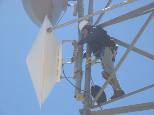
The best way to ensure the dish mounting mechanism is installed properly is to require plenty of pictures. Doing so will remove any doubt that it was done incorrectly. Most importantly, pictures of a level placed on both axes of the pipe mast proves it is indeed perfectly level. This will help rule out any issues with the mounting hardware. In addition, you should include a photo with level on the back of the dish. This will show that the dish is level.
When proper alignment becomes difficult to achieve, and all other possibilities have been eliminated, it’s time to consider the installer. It can be physically and mentally grueling to spend hours on a tower performing the same procedure over and over, and not improving the situation. Nine times out of ten, the installer and their support people on the ground resign to the frustration and lack of discipline of proper alignment and just settle for low RSL.
I have witnessed proper alignment take multiple attempts by inexperienced people, until the “right person” arrives. Of course, the more experience someone has, the better they get at it. In fact, some installers can pre-align a dish with a high degree of success using simple navigation tools like a compass and nearby landmarks.
A favorite saying I’ve heard is that, “Plan B is not Plan A, with enthusiasm”. Sometimes it’s necessary to give the project a rest and come back to it, or put a new set of eyes and hands on it.
It’s very difficult to install relatively large dishes in the wind. Likewise, dishes that sustain exposure to high winds can move over time. It’s critical that appropriate tie-back hardware is used on larger antennas. Some customers require that 3′ dishes and larger have tie-back hardware. Often 6′ dishes have two tie-backs and 8′ dishes and larger have three tie-backs. The use of tie-back hardware (sometimes called “struts”) requires forethought and planning, to ensure that all of the correct hardware is purchased in advance.
In areas where propagation is more susceptible to inversions and weather-related phenomena (varying k-factor), it is very important to perform alignment during periods of stable weather. Generally speaking, ‘good’ propagation is accompanied by wind and sun, cold fronts can be good – once they pass, warm & stationary fronts are ‘bad’. I credit my friend and colleague, Tom Hendricks for this information.
Anticipate challenges in antenna alignment when shooting over or through reflective surfaces (ie large bodies of water or between many tall buildings or a narrow canyon). With a good design the results are predictable.
We often use the microwave radio to provide fine alignment of the system. Most radios provide an indication of Received Signal Level (RSL), sometimes called RSSI. One should always be aligning to a planned RSL (dBm) value, which is derived from path planning tools or software. In addition to providing an RSL value, some radios also give audible feedback with a buzz or beep, or visual feedback with LEDs. Regardless, we generally only use these aids for course alignment and rely on an RSL measurement for fine alignment.
On occasion, the antennas are being installed before the radios are available, so the radios cannot be used for fine antenna alignment. There are some popular products available for antenna alignment under these circumstances, like the Spectracom Path alignR.
Similarly, we recently witnessed a demonstration from a company called Sunsight Instruments and their alignment tool called the AAT-08. We found it to be a highly innovative tool and seemingly valuable in terms of expediting alignment, versatility and reporting capabilities. We’re anxious to get feedback from the field about how they work.
To reiterate, the right tools need to be used. This is typically ratcheting-style wrenches and socket sets of the correct size. In addition, a small torpedo level to ensure everything is perfectly plumb prior to alignment. We often see people using digital levels. These seem to work well. Your installer should also use a marker to put an indicator on the threaded rod. This will remind them how to get back to a certain signal level.
Prior to getting on the tower or building, a course alignment can be achieved using a simple magnetic compass, adjusted for proper angle of declination. Of course, this assumes that the path azimuth is known. Google Earth can help identify nearby and distant landmarks that the installer can use to aim the dish.
We always align the antennas with no up-tilt or down-tilt, unless the path is extremely short. This is the easiest way to begin alignment if the expected tilt adjustment is less than a couple of degrees.
Only one side of the path should be adjusted at a time. In addition, everything below assumes that both dishes are on the same polarization.
Once everything is level, the azimuth should be swept. You’ll often see one or more side lobes of the antenna before you see the main lobe. This is indicated by the RSL measurement. The main lobe is often distinguishable as having approximately 20dB more signal than the nearest side lobe. Likewise, it tends to rise and fall off very sharply, where side lobes can persist longer through a sweep cycle. Also, the main lobe is accompanied by the presence of at least two side lobes on either side of it.
If you were to start a sweep on the far left side of the radiation pattern of a dish, sweeping the dish to the left (pulling the left side of the dish towards them), you should see some amount of signal gradually increase and then decrease (one side lobe). Next, you will see the signal increase more than it did with the prior lobe and then decrease (another side lobe). Finally, the signal should increase significantly (~20dB) and quickly fall off. This is the main lobe. After this, the reverse of what was just described should be witnessed as the dish continues to be swept in the same direction, until the signal completely goes away.
Commonly, installers will only see a single lobe in the entire sweep. This is seldom the main lobe and evidenced by a signal level well below (10 – 20dB) the planned RSL. A lot of time is often spent aligning both sides of the link to keep landing on the lower-than-expected RSL. This is often due to one of the issues described above. Either mounting isn’t level, there’s tilt in the dish, or adjustments are being made on both side simultaneously, etc.
Another common symptom of poor alignment is that two rises and falls of signal will be seen, but well below the expected amount. This is just more evidence of either being above or below the main lobe, or not sweeping far enough through the entire radiation pattern.
Once the main lobes of both dishes are found, the elevation should be adjusted to optimize the link. Once both azimuth and elevation are fine tuned, the RSL should meet the planned signal level dictated by the path design.
There are definitely other things that can go wrong with microwave radio links. More often than not, the problems stem from a system that isn’t optimized. The most neglected step in optimization is proper alignment.
We’d love to hear your thoughts on the matter. Please take a moment and let us know how you deal with an installer or tower crew that swears the path is “on the main lobe”, when all of the evidence points to it being on a side lobe.
Don’t forget to click here and sign up to receive our latest blog posts and free content.
"We guarantee your system will work as designed for the first year, or we'll make it right."
Please CLICK HERE to read our full Terms & Conditions